Skip to product information
1 of 3
Vendor: TENSE

Digital overcurrent relay with voltage protection and 3×3 digit LED display TRM-30F

SKU: TRM-30F
Regular price
£47.74
Regular price
Sale price
£47.74
Out of stock
  • Description
  • Payment methods
  • Warranty

Monitoring overcurrent relay TRM-30F with display, 3-phase up to 25A

It is designed to protect equipment sensitive to operating current and voltage values from errors that may occur due to:

  • current overload (adjustable current value 0.5 ... 30 A)
  • current asymmetry (50 %, fixed value)
  • voltage asymmetry (30 %, fixed value)
  • overvoltage and undervoltage (Umin: 265 V, Umax: 440 V, fixed value)

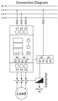
The TRM-30F digital overcurrent overload relay with display allows you to view the current in each phase and protect the motor or appliance against overcurrent, overvoltage, undercurrent, phase failure and phase reversal. These digital overload relays are designed to prevent damage to the motor/load from high currents while allowing the current flowing in each phase to be monitored on the display. They are also capable of checking the cumulative voltage values between phases.

Thanks to the two output relays (1x NO, 1x NC) it is also possible to control or disconnect the load when an overcurrent setpoint is reached, or to switch on a signalling contact to the control system. The TRM-xx digital relays have built-in current transformers and a 3x3-digit display for current display.


Application and operating principle

  1. Connect the device according to the connection diagram. Incorrect connections may damage the device.
  2. Set the overcurrent of the device using the ">A" control according to the operating current of the load you will be checking.
  3. When the power is connected, the set overcurrent value will appear on the upper display and the error waiting time on the middle display within the first second.
  4. The actual values of the currents from the phases will be displayed after one second of operation and the indication LED will light up.
  5. When the "V/A/RESET" button is pressed, the values of the combined voltage between the phases are displayed.

Drivers

  • "A>" - setting the permissible overload; the value is shown on the upper display.
  • "sec." - setting of the overcurrent fault wait time; the value is displayed on the middle display.

Contact status

  • NO 95-96, NC 97-98:
    • Device de-energized or in fault condition: NO open, NC closed.
    • Device energized and without fault: NO open, NC open.

Indication LED

  • LED "V" - illuminated in the event of overvoltage/undervoltage or voltage asymmetry error.
  • LED "A" - illuminates on high current or current asymmetry error.
  • LED "XI" - illuminates when the phase sequence is incorrect.
  • LED "NOR" - illuminates when the device is energized and the system is error free.

Function of the "V/A/RESET" button

  • Reset: pressing for 3 seconds clears the fault, LED "A" goes off, NO contact turns on, NC contact opens.
  • V/A: a short press switches the display between current and voltage values.

Protection and operating principle

1. Overcurrent protection (0.5-30 A):

  • Entry into fault state: when the set overcurrent is exceeded, the set time is waited. Phase display flashes, LED "A" is on, NO open, NC closed, LED NOR off.
  • Leaving error condition: current below setpoint, press reset for 3 seconds.

2. Protection against current asymmetry:

  • Input: current difference between phases >50%, wait 3 seconds, display flashes, LED "A" illuminated.
  • Leaving: difference <50%, press reset for 3 seconds.

3. Overvoltage protection (U>440 V):

  • Input: voltage >440 V, wait 3 seconds, display flashes, LED "V" lights.
  • Exit: voltage <435 V for 3 seconds.

4. Undervoltage protection (U<265 V):

  • Input: voltage <265 V, waits 3 seconds, display flashes, LED "V" lights.
  • Leaving: voltage >270 V for 3 seconds.

5. Protection against voltage asymmetry:

  • Input: voltage difference >30%, waits 3 seconds, display flashes, LED "V" lights.
  • Leaving: difference <30% for 3 seconds.

6. Phase sequence protection:

  • Incorrect phase connection will light LED "XI".

Current asymmetry calculation

The instrument calculates the asymmetry according to the formula:


Example: ((25 - 15) / 25) × 100 = 40% current asymmetry.


Technical specification

  • Supply voltage: measured voltage 3f 3x400 VAC
  • Operating voltage (Un): 3x380 VAC 50/60 Hz, self power <10 VA
  • Adjustable overcurrent (Overload): 0.5-30 A
  • Fault waiting time (t): 0-20 s
  • Display: 3x3 digits, 9 mm height, 7 indication LEDs
  • Overvoltage: 440 V (L-L)
  • Undervoltage: 265 V (L-L)
  • Voltage asymmetry: 30%
  • Current asymmetry: 50%
  • Waiting time for asymmetry error: 3 s
  • 2x output relays (1x NO, 1x NC): 3 A / 250 V AC (resistive load)
  • Connection type: screw terminals
  • Cable cross-section: 2.5 mm² (relay contacts) / 6 mm² (input and output loads for measurement)
  • Weight: max. 380 g
  • Mounting: on DIN rail
  • Operating temperature: -20°C ... +55°C
  • Operating altitude: <2000 m

Online card / PayPal payment - after completing the order, you will be redirected to the payment gateway, payment confirmation will be sent to your email.

Bank deposit- you will transfers money from you bank account into our bank account to complete your purchase. You will receive an invoice to your email no later than the next working day.

We warrant that on delivery, and for a period of 12 months from the date of delivery any products which are goods shall:

  • conform in all material respects with their description and any relevant specification;
  • be free from material defects in design, material and workmanship;
  • be of satisfactory quality
  • In the event of any goods being materially defective, we will replace or repair the product or refund the purchase price.

These warranties shall not apply to any defect which arises from improper use, failure to follow the product instructions, or any repair or modification made without our consent.

You might also like

Recently viewed products